Designing the Roller Conveyor Unit
Roller Conveyor Unit
The roller conveyor unit has two job in this process:
- Transferring the lemons from A to B
- Rolling the lemons so the camera can record images of them from 360°.
I do not want to invent an existing solution from scratch. Instead, I want to adapt one so it fits my case better.
This video shows exactly the kind of behavior I want:
It transfers the fruit and rotates it at the same time.
Model (blindly)
Single roller cylinder
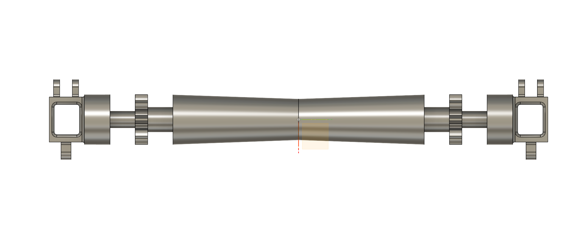
First, I wanted a shape that would direct the lemon toward the center, which is why I came up with an hourglass-like form.
Concept
The lemon model diameter is roughly 30 mm, so I set the single cylinder diameter to 20 mm and left 2 mm of space between each roller cylinder. This should allow the lemon to roll smoothly.
The main concept is that the conveyor cylinder should rotate the lemon backward while also transporting it from point A to point B.
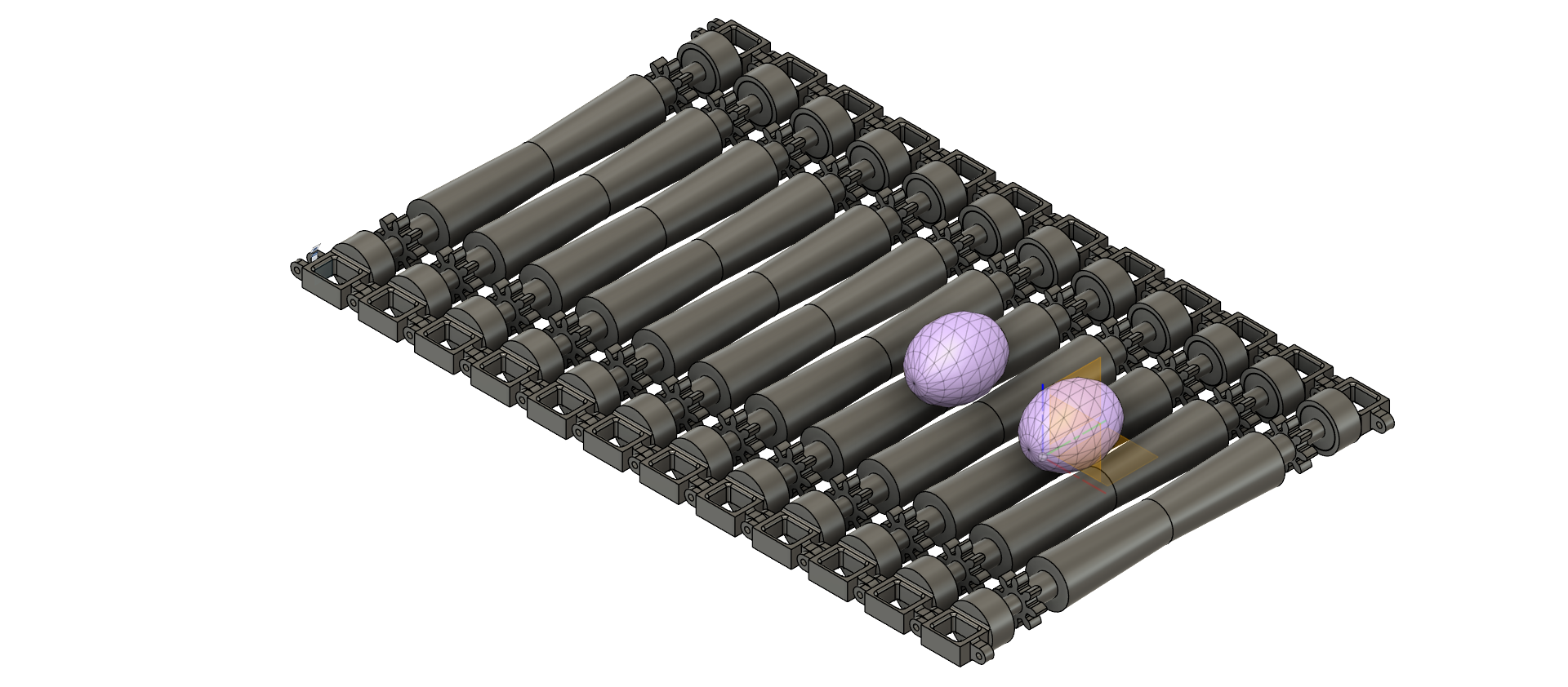
This is why I first use a spur gear to spin the conveyor cylinder. It will slide on a rack and pinion when the cylinders are on the upper side of the conveyor. Later, I will make an animation to explain this mechanism more clearly.
Second, I want to use a bearing so the entire cylinder can spin together with the spur gear and the rack and pinion.
Lastly, the sprocket should be attached to this body.
Conveyor cylinder details
I am noting this here, and honestly, this is my first time using CAD software, so I am probably wrong about many points. Still, I want to start somewhere, and I do not yet have enough education in this field. I am working with what I have for now.
I chose the cylinder dimensions so there is enough space for the spur gear, sprocket, rack and pinion, bearing, and chain.
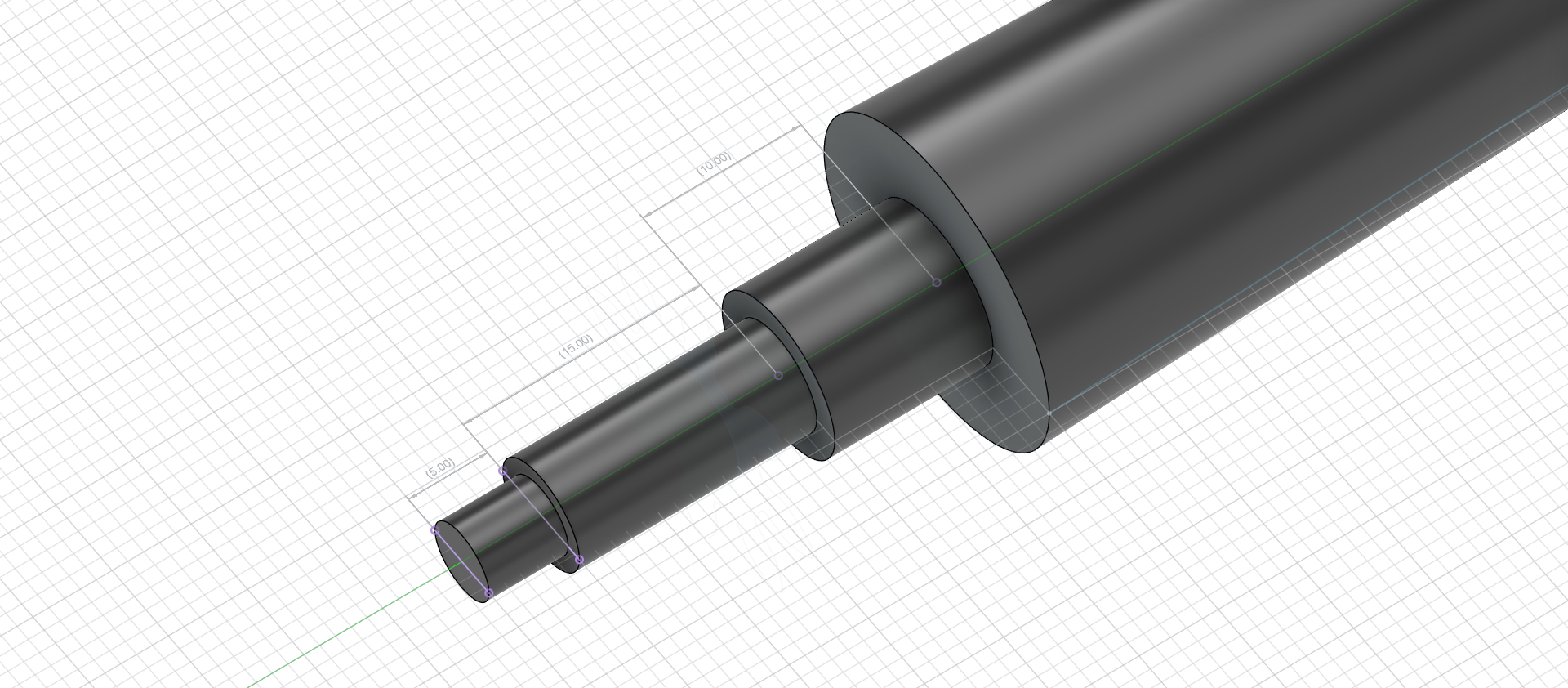
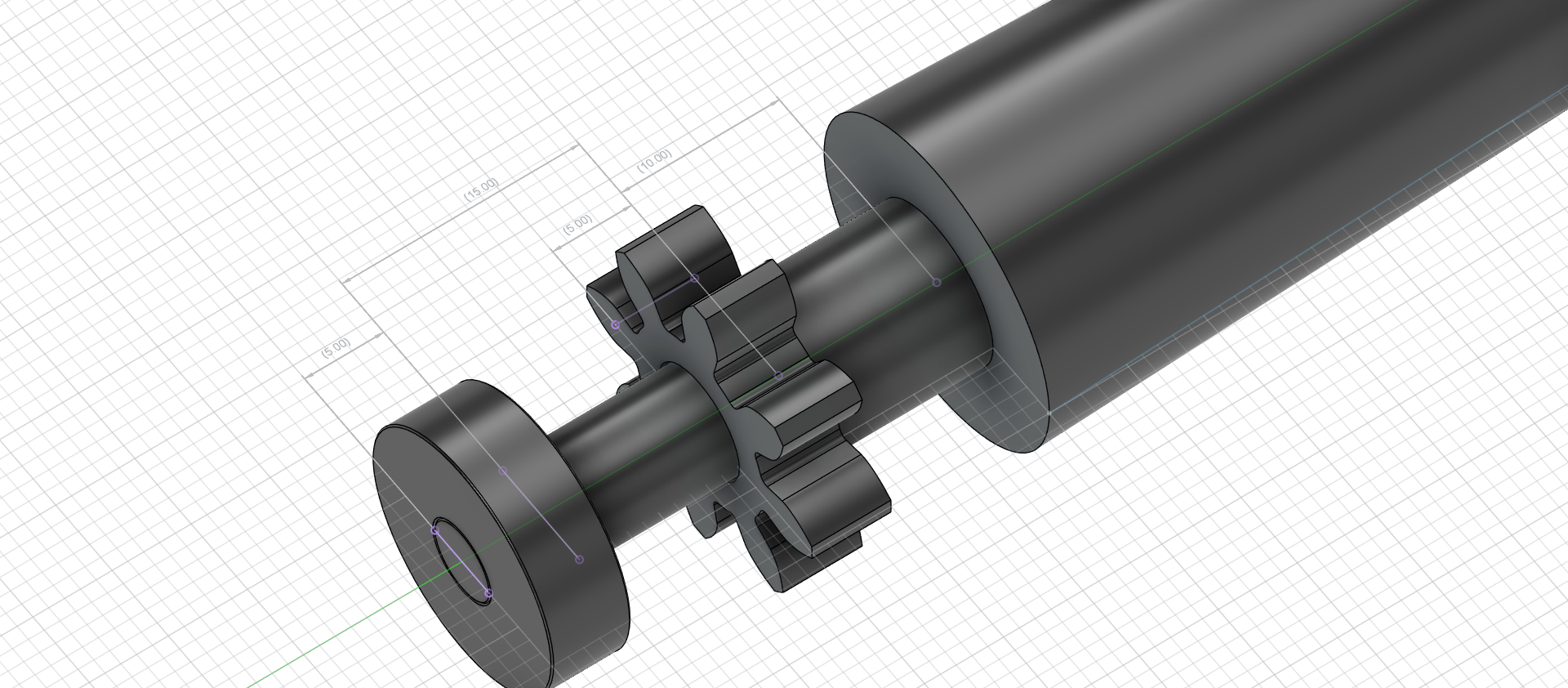
I tried to recreate the roller chain from scratch, and this was the point where I started to struggle really hard.
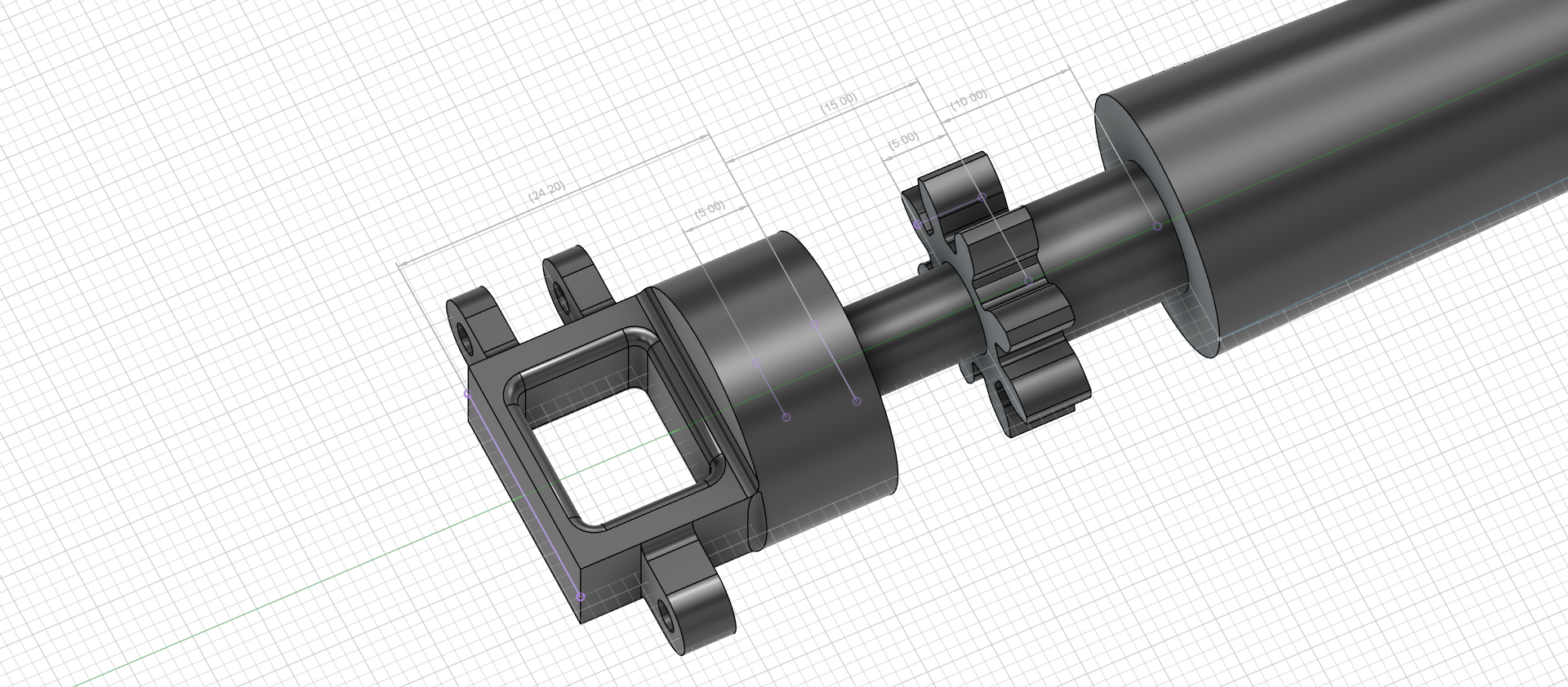
The struggle and the solution
I did not know much about spur gears, sprockets, or roller chains, so I started looking into the topic.
First, I learned some fundamental knowledge: ISO standards. I do not need to invent something that is already highly engineered and working well. I can assemble standardized parts, and there are probably better solutions than the ones I could come up with myself. I also read the formulas for calculating the perfect spur gear or sprocket, but at my level, it is simply not worth it. For now, I just want to build something, learn at my own pace, and experiment.
Modelling using ISO parts
At first, I thought I would 3D print the spur gear, sprocket, and roller chain. I will not. The reason is simple: it is unnecessary, and the moving parts would wear out very quickly.
Using ISO parts
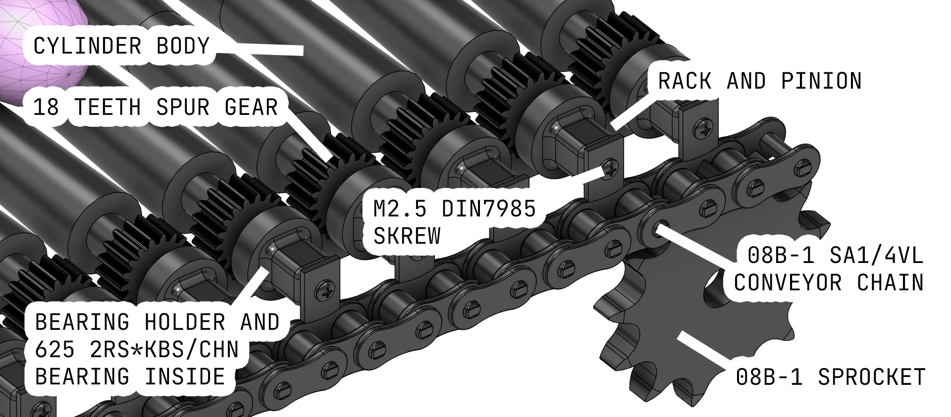
These are the parts I found for assembling the roller:
Sprocket
I will use four sprockets for my roller conveyor unit to move the cylinders forward along the line: two sprockets for connecting to the motor drive and two sprockets at the other end.
I chose the 08B-1 sprocket with 13 teeth.
I found excellent documentation for the 08B-1:
Conveyor chain
I need to use two chains, one on each side of the conveyor, and connect them to the roller cylinders.
The idea is that the chain should have an attachment that can hold the cylinder body, connecting to the bearing.
It should be compatible with the 08B-1 sprocket, which is why I chose the 08B-1 SA1/4VL conveyor chain.
I will fasten the bearing holder to the hole on the chain with a screw.
There is also excellent documentation for this:
Bearing
The bearing inner diameter should be 5 mm, which matches the connection to the cylinder body.
The outer diameter should be 16 mm, which will be inserted into the bearing holder part.
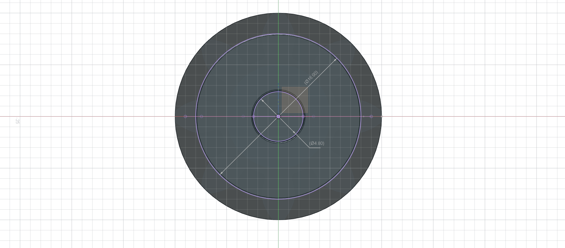
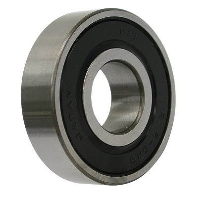
A perfect fit is a 625 2RS*KBS/CHN bearing, with dimensions of 5 mm x 16 mm x 5 mm.
Spur gear
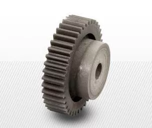
For the spur gear, I chose one with module = 1.0 and 18 teeth. Its purpose is only to spin the roller cylinder.
It’s made from PA6 + 30% fiberglass.
Rack and pinion
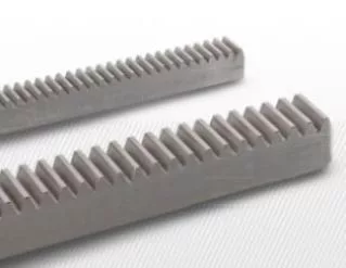
To match the spur gear, I chose a module = 1.0 rack and pinion. It is reinforced with fiberglass and steel.
Re-thinking the concept
Overview
After all this, I recreated the concept model, so this is how it looks after using ISO parts:
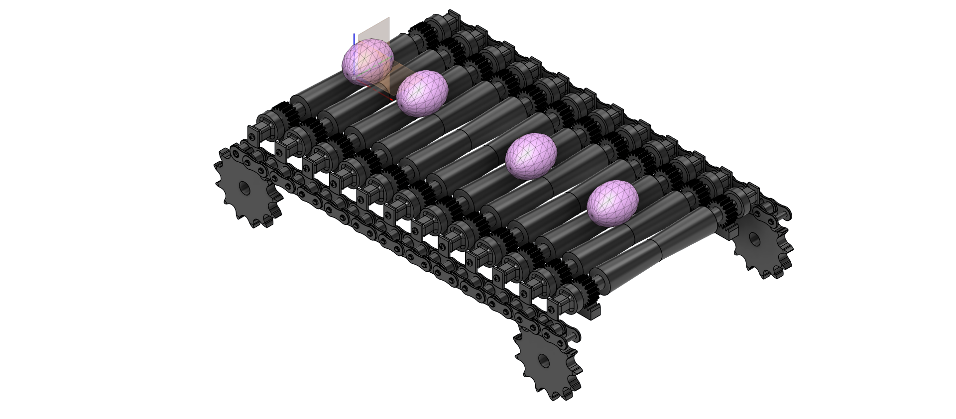
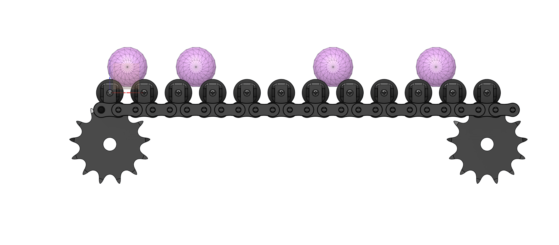
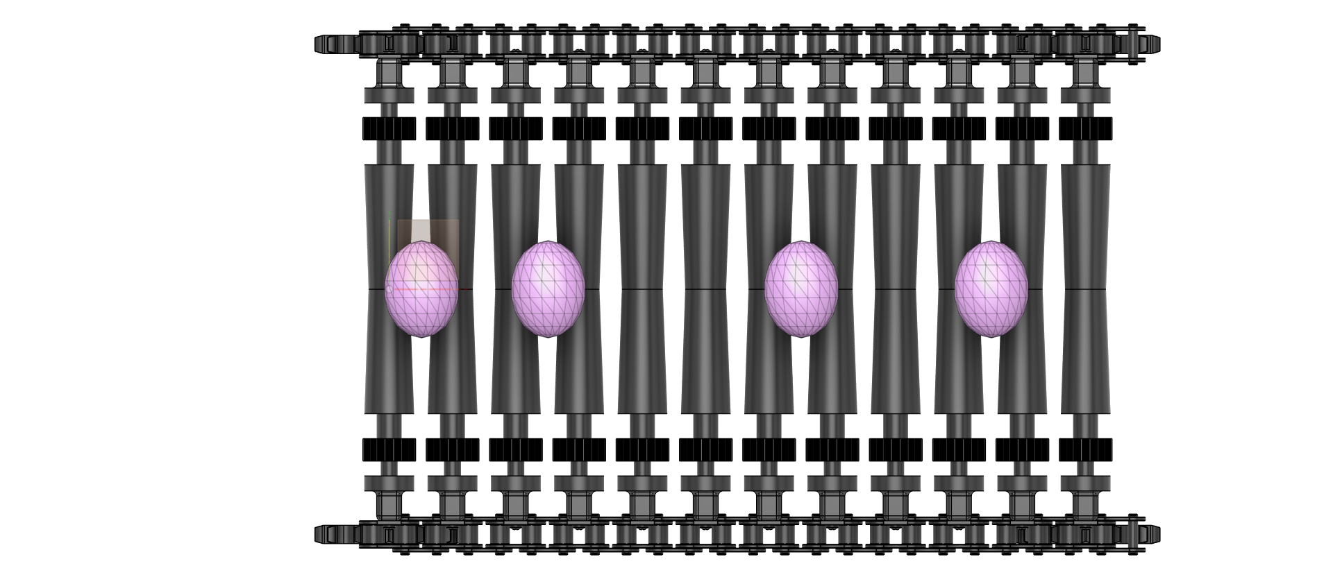
Once I learn more CAD techniques, I will make the chain bend over the sprocket and animate the process. Right now, my knowledge is not enough for that.
Close-up view